What To Do
1. Use an output device that you haven't used before.
2a. Write a microcontroller program that integrates at least one input device and one output device.
2b. Avoid using the delay() function.
What I Did
I made two buzzer pianos with different inputs: one with buttons and another with capacitive sensors. The button piano was more of a proof-of-concept for the capacitive sensor piano, as I had never used the buzzer before this project and wanted to get the hang of playing diffferent notes using it.
Even though I ran into many issues with the code, I really liked this assignment. I created two, fully-functioning, portable desktop pianos that can be taken basically anywhere to play. They don't really sound that good, but they're really fun to play and make music with.
Button Piano
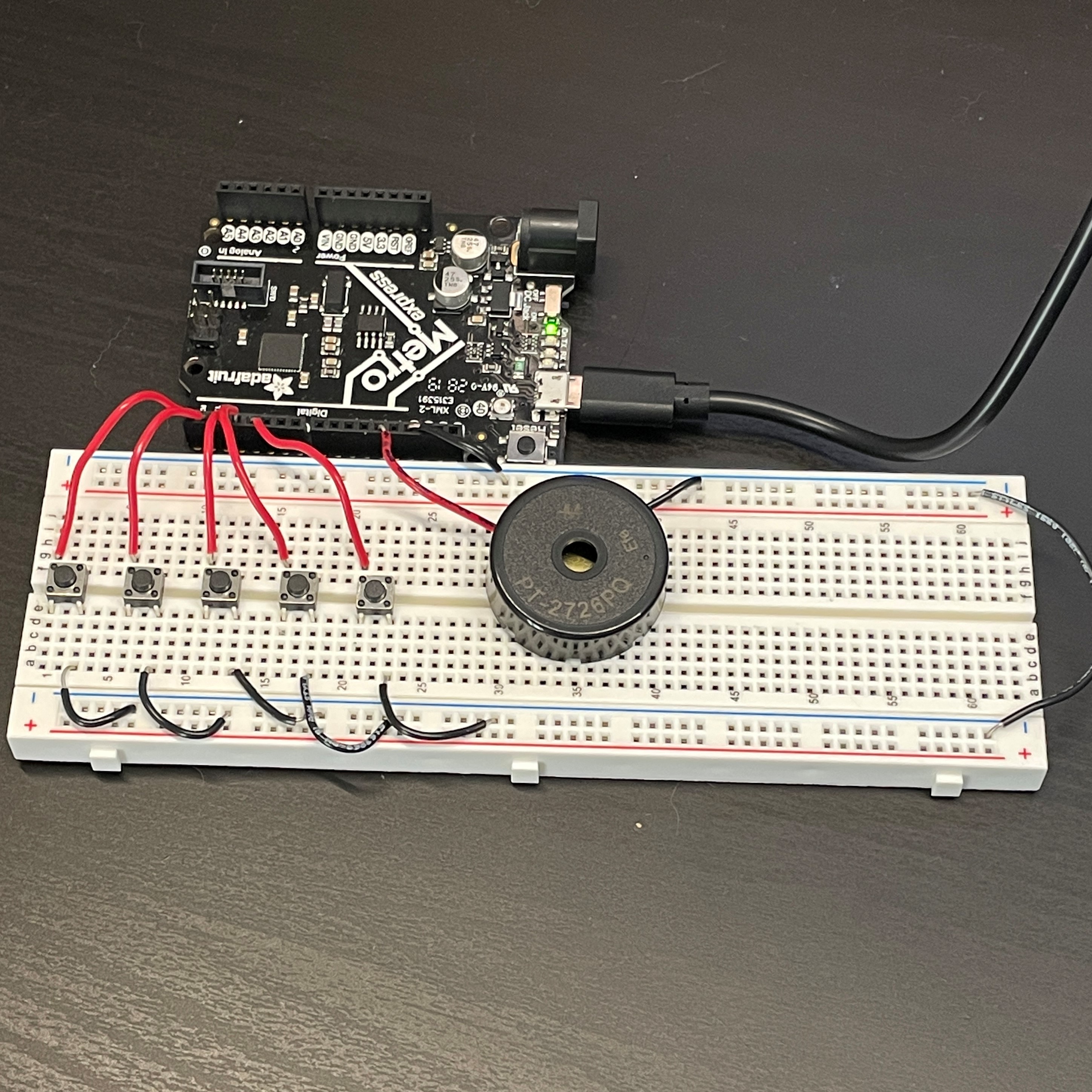
To the right is the button piano I made. It's super simple: just 5 buttons and a buzzer. I didn't use any physical resistors because I used the built-in pullup resistors for the buttons. Other than that, it's just the coding part that was a bit tedious, but since this served as my reference point for later when I made the capacitive touch piano, I wanted to do it right.
The Arduino embed below shows the code I wrote for this button piano. Like I said, it's super straight forward. I set the pins as input pullups for the buttons, and create variables for the state of each button. Then, I add the if() statements that essentially mean "if the button is pressed, then play a note."
Another thing to mention is that I referenced the pitches.h tab, the second tab in the embed, which has frequencies of the buzzer defined to notes on a piano. The way the buzzer works is by producing a sound frequency, and there are certain frequencies that correspond to exact notes on the piano. The pitches.h code is publicly available by Arduio and given with the tone example sketches. Because I had 5 buttons, the 5 notes I chose were C, D, E, F, and G.
There was one serious problem I ran into when making the button piano. When I pressed the buttons, no sound played. When I released the buttons, the sound played. This is a key error (hah, it's a pun. "key" error, because it's a piano with "keys") because I wanted the notes to be played when the button was pushed down.
I spent a lot of time trying to figure out a solution to this button problem but to no avail. I even tried out the code of other peoples' button pianos, as linked in the projects I referenced at the bottom of the page, and still had no luck. This can be seen in the video below.
Because of the weird button function, I couldn't use the noTone function because that activates after I release the button, which meant that there would be no sound played at all.
Also, just to clarify, the button was still detecting if it was being pressed or not (I used a serial monitor to degug this), but it was just an issue with the buzzer playing after the button was released.
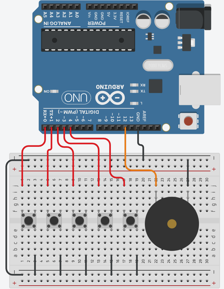
To make the whole circuit easier to view, I added a Tinkercad model of my circuit to the left. It uses the exact same pin connections as my real button piano does, so you can directly copy my Tinkercad model and code and have a functioning piano. The wire color-coding is pretty simple: red is positive for the buttons, orange is positive for the buzzer, and black is ground. On my actual button piano, I used a regular red wire for my buzzer positive. I just used an orange one in the Tinkercad model to differentiate between the buzzer poositive and button positives.
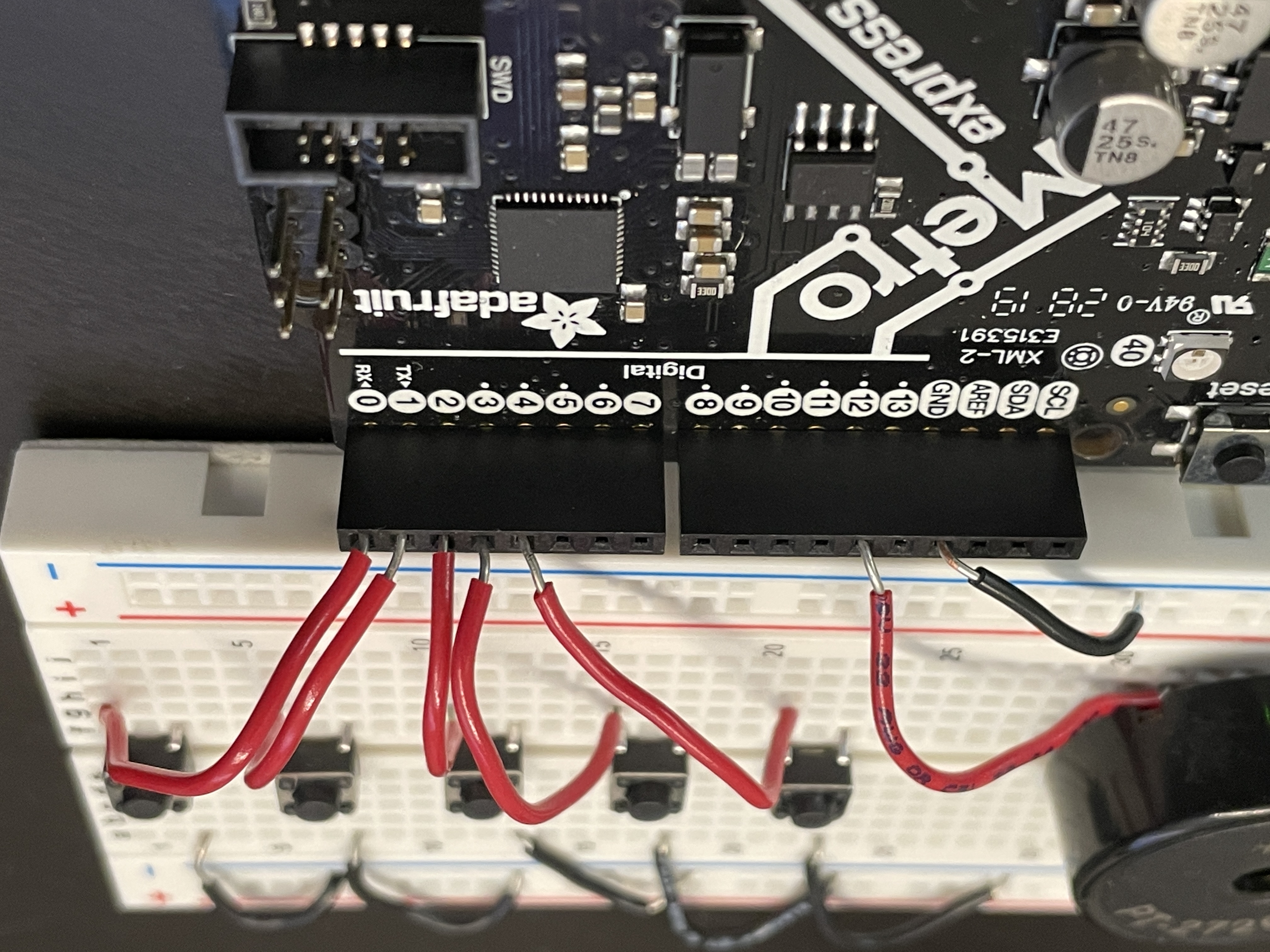
The actual pin connections can be seen with a close-up in the above. One thing to note is that I could've also just connected my buzzer directly to the Metro board using one of the analog pins and the ground pin. I do this for my final capacitive piano.
Below, there are three embeded videos of some basic songs I played using my button piano. I was limited to a song using only the first 5 notes in the C-major scale, as I only was using 5 buttons as dedicated keys.
Mary Had A Little Lamb
Jingle Bells
Hot Crossed Buns
Since I wasn't able to solve the issue with the buttons and I figured that what I had was already a good enough proof-of-concept, I decided to start on the capacitive sensor piano. I started off by making a prototype, which I talk about next.
Capacitive Sensor Piano Prototype
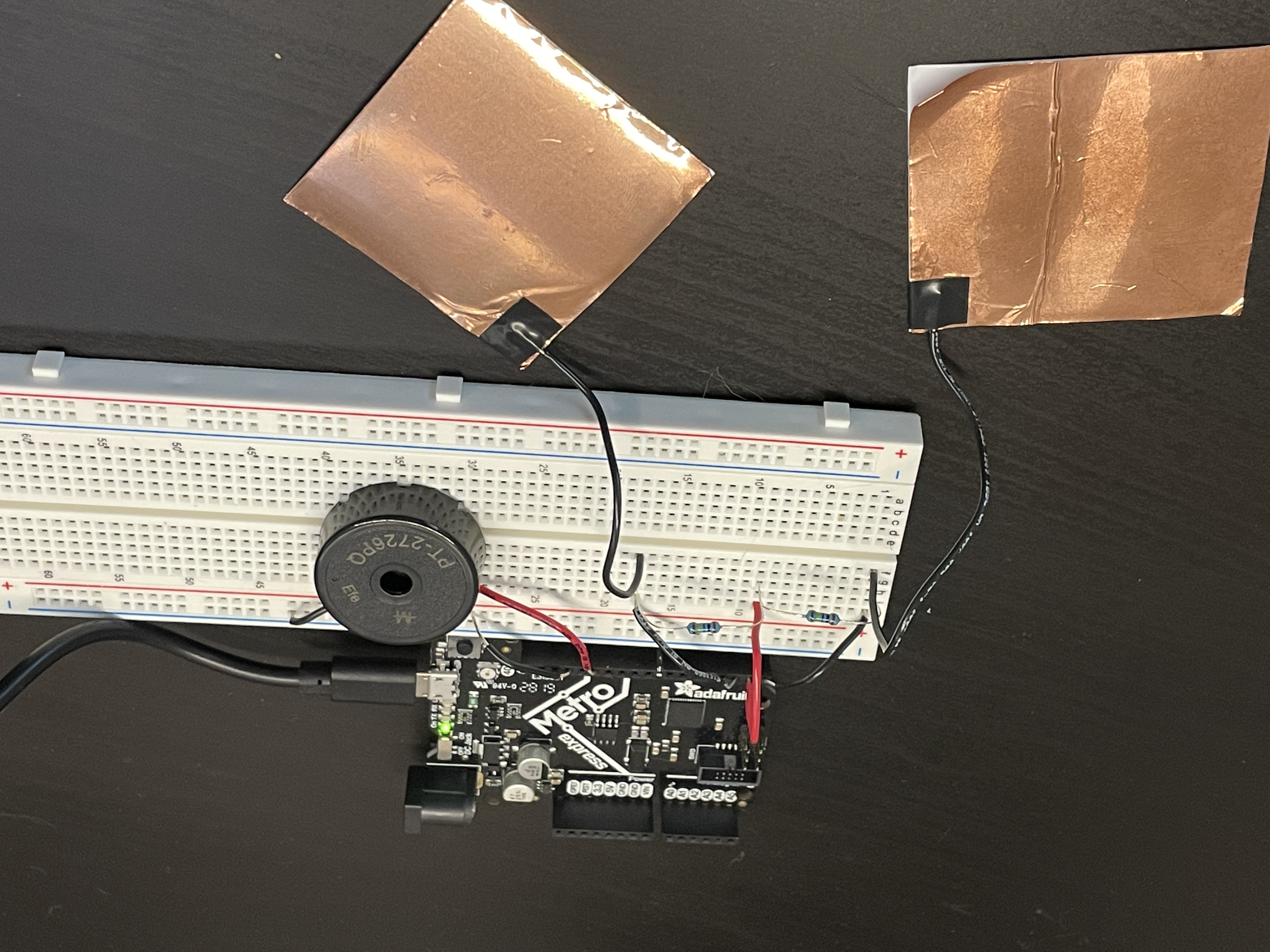
To the right is the prototype capacitive sensor piano. It only used two sensors, two resistors, and a buzzer. Since I used capacitive sensors in the last assignment, I was a bit more familiar with how they worked coming into this assignment.
The code for this prototype is below. Because my prototype only used two sensors, I only used two notes in the code: C and D. I also found that the best threshold value for the sensors was 10k. Using 1m Ohm resistors, the range started from 0 to about 60-80k. So, anything below 10k doesn't register as a touch, which is a good amount because it never accidentally detected a touch.
I was also finally able to use the noTone function, and it worked perfectly. After a stopped touching the sensor, the buzzer stopped playing.
Because I already had some experience with capacitive sensors before, I didn't have any issues with them this time. The videos below show the sensors working at different thresholds. The first video shows the before calibration, and the second shows after calibration. I don't exactly remember what threshold I used for the first video, but it must've been lower than 10k because it was a lot more sensitive and less accurate than my 10k threshold version was.
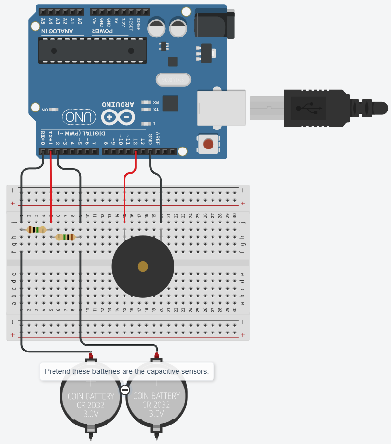
I also experimented with using only one charge wire for both sensors instead of using one for each as I did last assignment. In the model to the left, the red wire connected to pin 1 is the charge wire for both sensors. The black wires on pins 0 and 2 are the detection wires. In this model, the resistors form a voltage divider. Also, pretend the coin batteries are the capacitive sensors.
At first glance, it would seem that touching one sensor would trigger the other because they are connected using the two 1m Ohm resistors. They do, but they only send a very low capacitive signal (I talk more on this later).
Now that I had all of the information I needed, like whether or not I could use one charge pin (the answer is yes), what resistors were best suited for my project (1m Ohm resistors), and what threshold was a good threshold (10k), I started on the build process for my final capacitive sensor piano.
Capacitive Piano Build Process
To the right is the capacitive piano base I made. The idea was that instead of just having sensors laid on a desk, I wanted to have a physical dedicated object to play on. My model simulates a real piano, as the "keys" on my piano bend downwards as if a real key is being pressed.
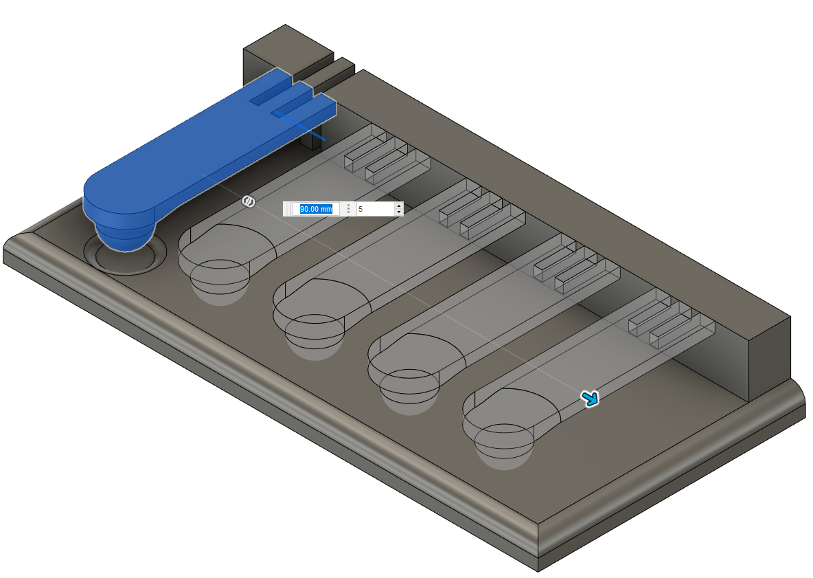
Designing the piano base was pretty simple. I first made the rectangular base. Then I extruded a smaller rectangle on the back (this is where the keys attach to). And then, for each key, key divot, and back cut-outs, I just used the rectangular tool to essentially duplicate the first key 4 other times as seen above.
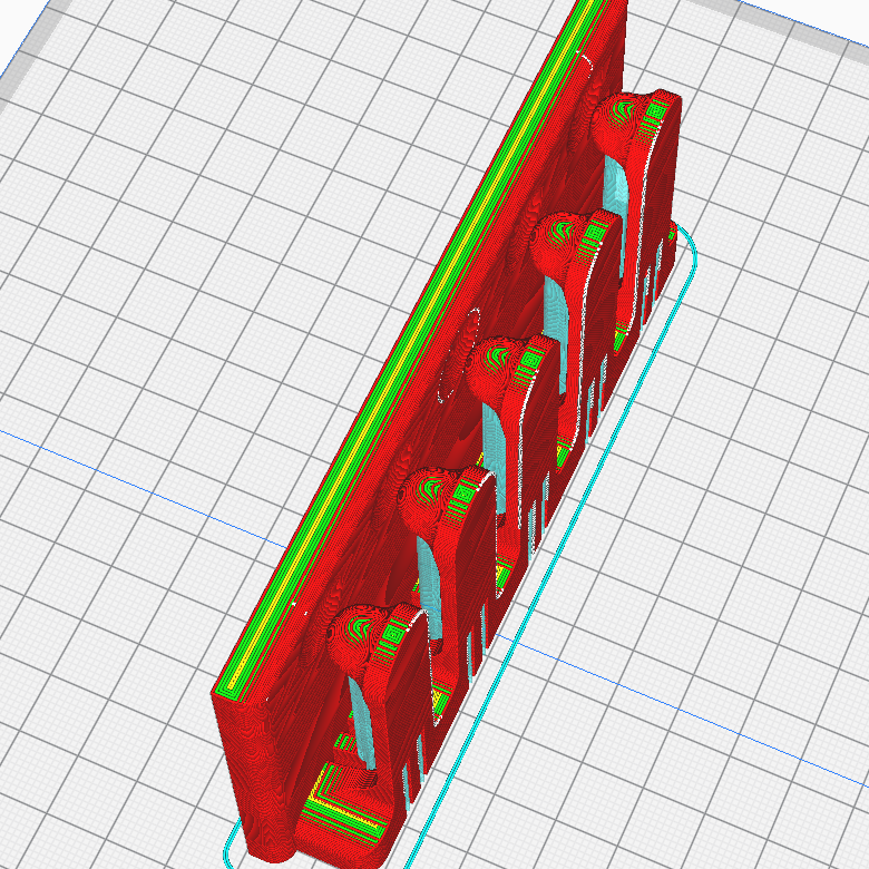
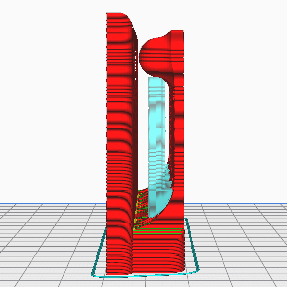
When designing the piano base, I had to keep in mind that I would be 3D printing this out, so I needed to keep one part of the piece completely flat. At first, I wanted to print it how most would think: with the actual base part on the bottom and keys on top. But, that oreintation used lots of supports, and I figured that removing supports from below each key would be challenging to do neatly.
So, I printed the piece with the back on the bottom. I used 0.3mm layer height at 50mm/s. It took about 6 hours.
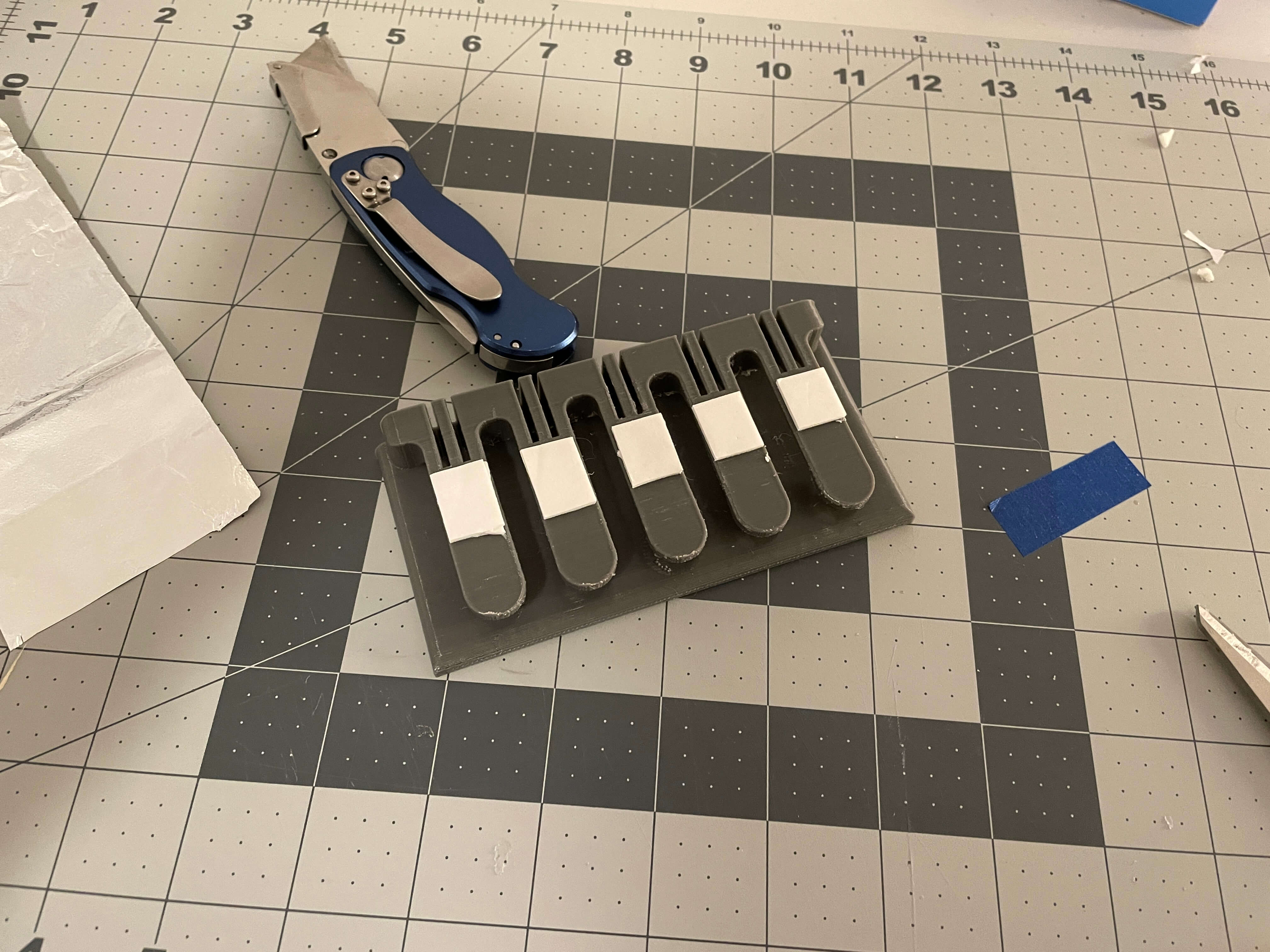
Below are videos that show the piano base part after printing. It turned out fairly well, although there was a lot of stringing and some support residue that I couldn't remove.
Capacitive Piano Wiring Process
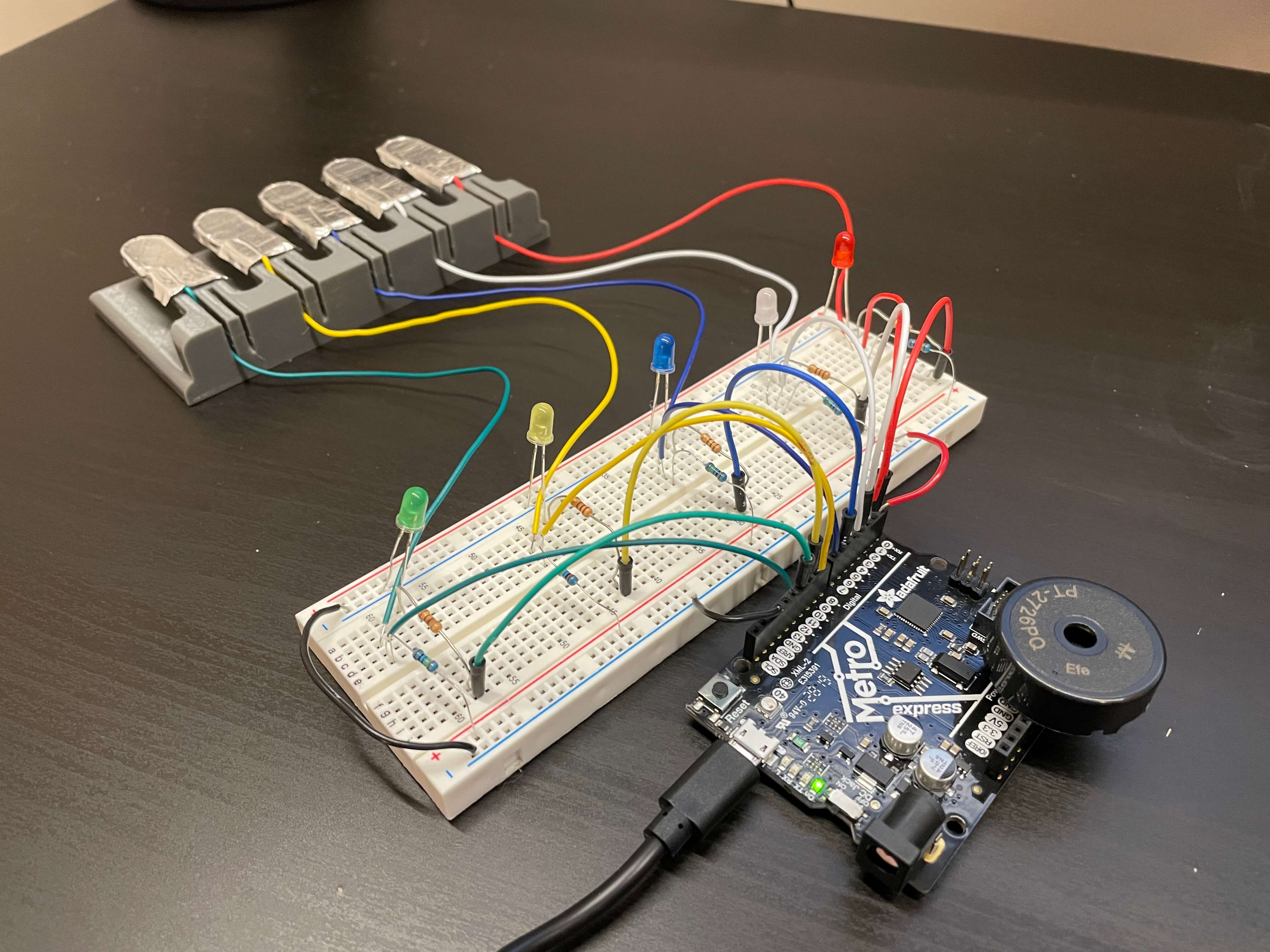
Something to note is that I designed and printed this before figuring any of the wiring out for this piano. I figured since the prototype worked, I didn't need to make another test circuit with 5 sensors instead of 2. Another thing to note is that I went ahead and bought a spare parts kit and extra wiring for my projects. So, to make things easier to understand, I color-coded each key to a different wire color, starting from red, then white, then blue, then yellow, and lastly green.
To start the wiring process, I started by making the sensors themselves. I used double-sided table to connect the wires to the aluminum foil sensors to each key, so the tape served three purposes. I first put tape on each key. Then, I placed the stripped end of each wire onto the tape and placed the aluminum foil strips on top. This firmly attached the stripped wire to the foil, meaning that the sensor readings should be pretty accurate.
I then routed the wires through the notches in the piano base. The notches serve three purposes: I'm pretty sure they help the keys bend, they serve as a wire router, and they look cool.
Below, the gif shows the key movement. The keys don't have that much travel, about a couple milimeters, but anything more and it wouldn't go back to it's original position without permanent damage. This was about the perfect about of travel to where when you play the capacitive piano, you can feel each key moving. I think it turned out great and has a super neat effect on the whole project.
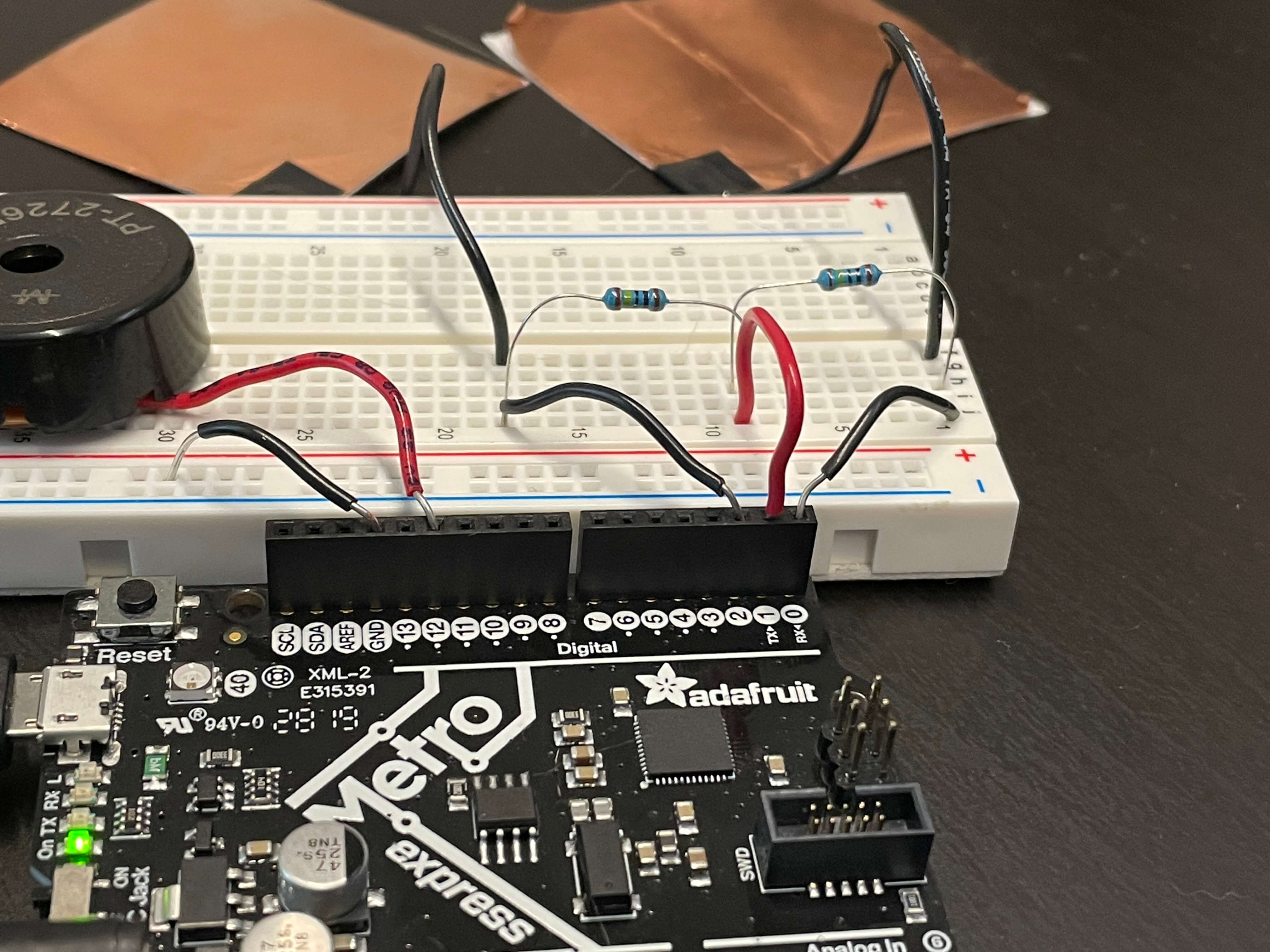
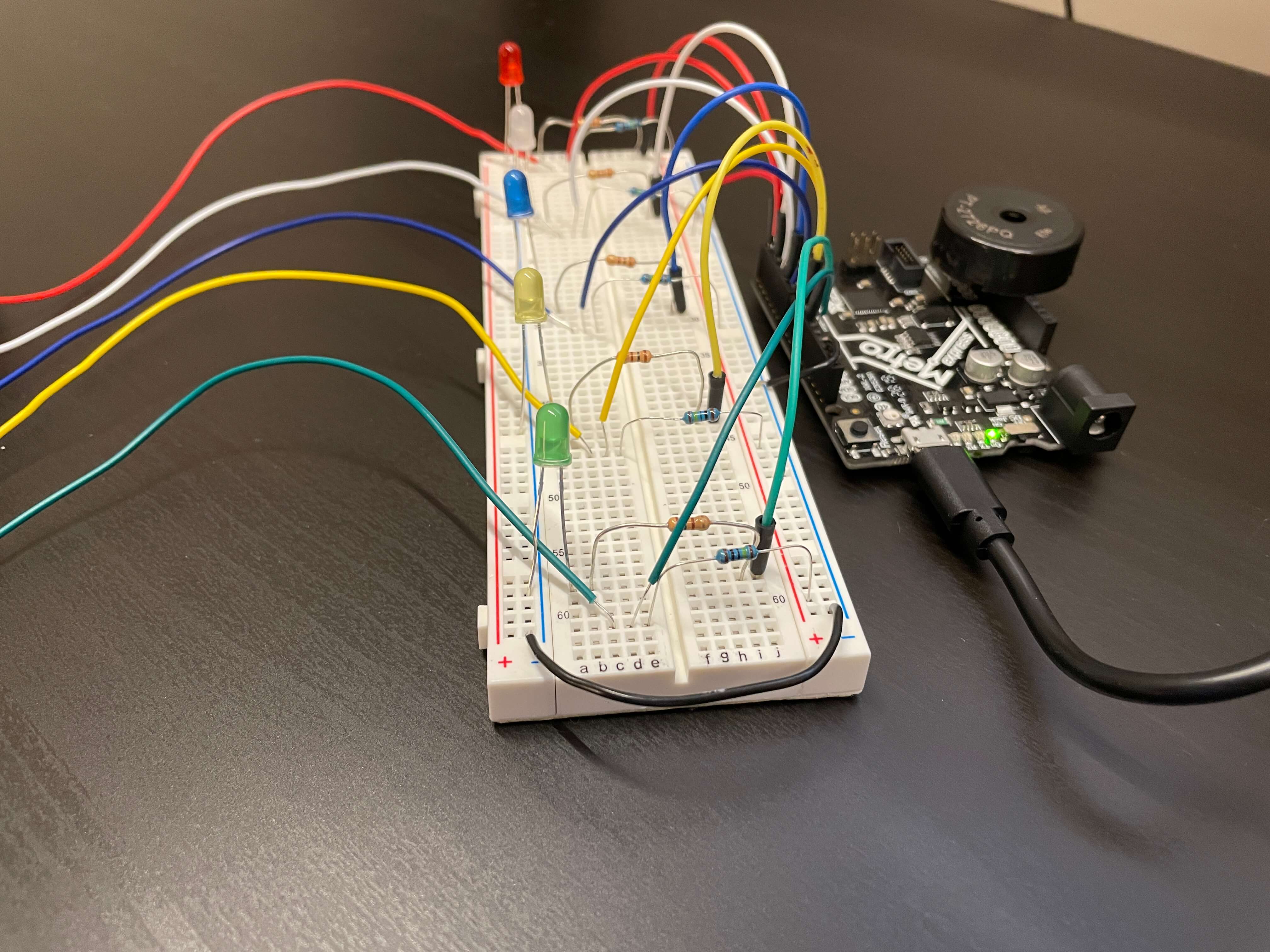
After creating each sensor, I started on the breadboard circuit. This was, again, pretty straight forward as I have already made capacitive sensors before. But, it's just a bit confusing because there's many wires. Like I said, I made the whole circuit more organized by color-coding the sensors and their respective circuits accordingly.
I also hooked up correspondingly colored LEDs to each circuit just to make it look cool. This added five extra wires and five extra resistors, but I still found a way to organize them by using dedicated male-to-male pins with black headers and blue resistors for the LEDs.
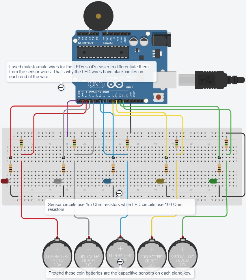
I added a Tinkercad model of my capacitive piano below. I'm not sure whether it really helps, because it's still pretty confusing with all the wires. Anyway, for the LED circuits, I used 100 Ohm resistors and for the sensor circuits, I used 1m Ohm resistors. Also, like before, pretend that the coin batteries are the capacitive sensors.
Like in the prototype model before, I used one charge pin for all the capacitive sensors in this model. This saved using many wires and is shown below by the purple wire connecting from digital pin 0 to the positive power rail.
That was it for the electrical process. It looks pretty complicated, but the whole circuit is just one sensor and LED circuit duplicated 5 times. Next, it was time to start coding.
Capacitive Piano Programming Process
Starting the programming process was a bit overwhelming at first but not too bad. I already had a lot of the code written for using a capacitive sensor to light up an LED, so I just copied that over from last assignment. This time, I had to add the buzzer. Again, not too bad because I already had the piches.h tab, which has certain buzzer frequencies defined to notes, and in class, we wrote code to make the buzzer play one sound. Using these two resources, I made the buzzer play 5 notes by using 5 capacitive sensors, which also light up 5 LEDs.
The code starts by defining a bunch of variables, including each pin mode and sensor. To make it convenient for me, I defined each sensor to the color of the circuit that each was on. Then, it's really just 5 if() statements for each of the 5 sesnors. For example, if the far left sensor if touched (the first if() statement), then the red LED is turned on and the note C5 is played. Again, I used the threshold of 10k for all sensors. And, finally, for the noTone, another if() statement is used for when all sensors are detecting below 1k (no touch), then the buzzer turns off.
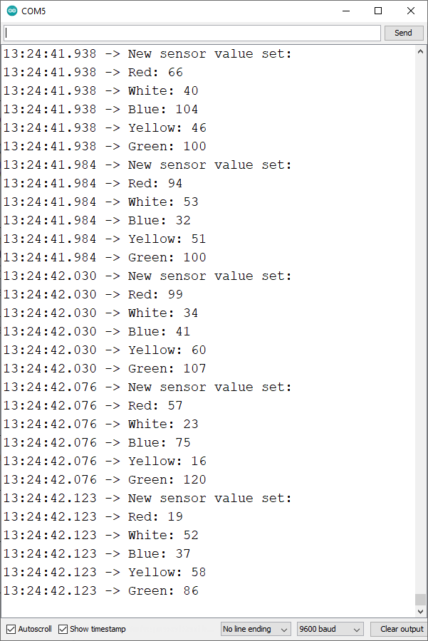
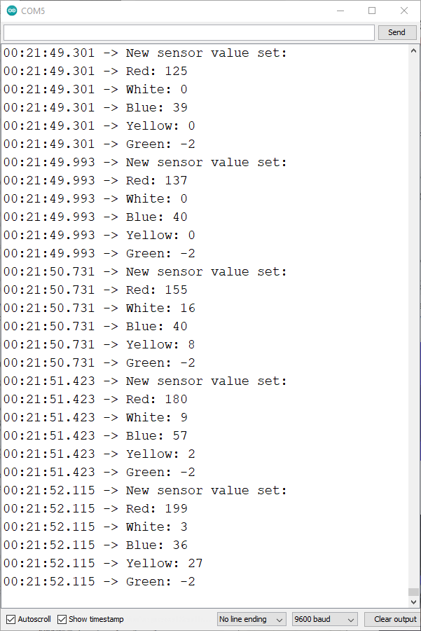
Below is the serial monitor output for when no sensors are being touched. Just to clarify again, I labeled each sensor based on their circuit color. So, for each new sensor value set on the serial monitor, top-to-bottom represents left-to-right on the capacitive piano. The normal non-sensing values range from 0 to about 130, which is why I used 1k as my limit for the noTone.
Down below, I embeded some songs I played with the final capacitive piano. Again, I was limited to the first 5 notes on the C major scale, so C, D, E, F, and G. It still turned out to be fine, and in any case, the piano can be expanded to have as many keys as there are open pins on the Metro board (or any other board).
Ode To Joy
Five Note Scale
Hot Crossed Buns
Down below, I embeded some songs I played with the final capacitive piano. Again, I was limited to the first 5 notes on the C major scale, so C, D, E, F, and G. It still turned out to be fine, and in any case, the piano can be expanded to have as many keys as there are open pins on the Metro board (or any other board). All in all, this was a fun project. It was fun to mess around using the various pianos I made, even though the buzzer was quite annoying.
Interesting Observations
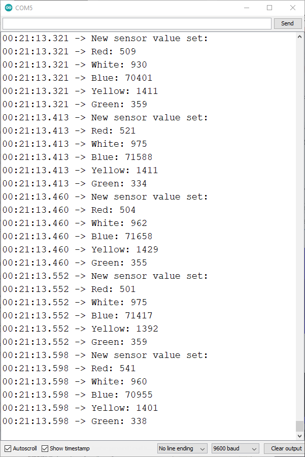
To the left is a serial monitor reading from about 12:30 AM in the morning. I am pressing down the the middle key and the sensing output value is spiking to about 70k. What's interesting is that the sensors next to the the blue key, the white and yellow keys, are also outputting some sensory value. Same is happening with the red and green keys. I think this may be happening because the senors being so close and reading the signal from each other. Also, this could have something to do with the fact that I'm using the same charge pin for all sensors.
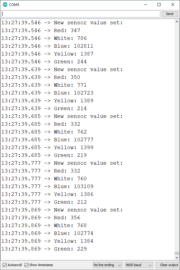
What's more is that on the serial monitor to the right, which is about 13 hours after the first reading, so about 1:30 PM, the same sensing pattern is showing, but the blue sensor is sensing over 100k. I think this has to do with the room humidity changing, which is pretty neat.
One cool troubleshooting option I found was to look at the serial monitor. Sometimes, when I was playing the capacitive piano, the buzzer would just stop working properly and the LEDs would start to blink. This meant that one of the sensor connections was loose. One way to tell if that's the case if on the serial monitor, one of the sensors is outputting a negative value, as seen with the green sensor in the serial monitor to the right. This was a life saver as this was a super quick way of solving an otherwise time-consuming issue.
Another cool observation was to see which keys took priority over the other. The keys have a precedent over each other from right-to-left. This is because in the code, the last if() statement is for the last capacitive sensor, the green key, which means while that key is pressed, no one sensor inputs play sound. This is because it's at the bottom of the loop, so pressing the key keeps the buzzer in that if() statement. The opposite happens for the red key, where if the red key is pressed, then all other keys still work as the red key's if() statement is closest to the top out of all the if() statements.
References
For guidance, I referenced numerous piano project videos uploaded on YouTube. Below, I also embeded the videos I watched for help. They were all great inspiration for my two pianos and helped me a lot when I didn't know how to fix certain issues.
I referenced many projects on the Arduino Project Hub that were related to a button/capacitive sensor piezo piano. I embeded some of the Arduino Projects I referenced for my pianos below. For anyone also creating and programming a piezo piano that uses buttons or capacitive sensors as inputs, I highly recommend checking out the projects below.
What I Learned
» How the use the piezo buzzer
» How create a piano using various input devices
» Why using the same charge wire for different sensors works
» How to troubleshoot capacitive sensors using the serial monitor
» How to properly use the noTone function